Radionics & Modern Science
The construction of Radionic Instruments has been one of the great difficulties in our work. Elementary radio and electrical components were the only parts available in the early days, and it is natural that these should have been used.
For years scientists, doctors and laymen have asked, “What is inside your ‘Box’ … can I have a look at the circuits?” My reply has invariably been, “Yes, certainly.” And having looked, in most cases the reactions have been uncomplementary.
“This is rubbish, a lot of nonsense, it couldn’t possibly work.” And immediately they would turn their attention elsewhere.
I have always held, and still do so, that science MUST and WILL eventually find the keys to solve the radionic riddles. I make this optimistic statement because science and radionics are today very close to being linked.
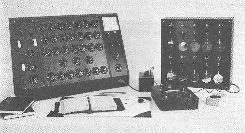
Mike Roberts, an expert and inventive Electronic Engineer whom I mention in my Introduction, and who has spent a great deal of time on Radionic instrumentation, has made one for me. We introduce a new concept in its construction, as well as assuring, as far as possible, electrical circuitry. But before describing it, let us run over the construction of the dial mechanisms that have gradually evolved during the 70 years of radionic endeavour.
To begin with Abrams used a variable resistance box in his initial experiments, and later, variable capacitors and inductors in some of his more advanced instruments.
Dr. Drown in her HVR Instrument used a series of ‘studs’ mounted in a circle made from hardboard or plywood, with a copper wiper moving over these studs. The studs were connected, one to the other, with stiff wire, and the dials were connected in series. These dials were not ‘electrical’ components but were especially made for her instruments.
Guyon Richards followed Abrams work and used a resistance box. He also experimented with various forms of valve amplifiers to amplify the radionic waves. Faraday cages and screens came into his experiments and a fuller explanation of his work is outlined in his book The Chain of Life.
Delawarr started by using a series of stub aerials. Later he devised a form of ‘split washer’ arrangement that covered the full 360° of arc but for some reason dial calibrations still had a gap between start and finish. At a still later date the Delawarr laboratories changed to radio type potentiometers.
In more modern times Malcolm Rae used potentiometers for his Base 44 instrument, but there is a difference here in the dial calibrations. Instead of the usual 0 – 10 markings, Rae devised a system that employs the numerals 1 – 44.
———————–
From the front a Radionic Instrument has a mass of dials and switches and one could be forgiven for thinking it is a complex form of electrical instrument. Delving into the back reveals a series of interconnecting wires and this further strengthens the illusion of electrical circuitry. They SEEM electrical… therefore they ARE.
But what has to be remembered is that these dials and wires are not carrying electrical signals as the scientist understands them. They were never designed to do this, but to work on a different basis. The use of such circuits, unconnected to any mains and therefore not apparently producing a viable electrical energy makes it hardly surprising that scientists were not interested in radionic instruments.
This aspect has not been brought out strongly up to now, for I suspect, the simple reason that people using these instruments THOUGHT they were electrical because they LOOKED electrical, when, in fact, they were nothing of the sort.
Here we have a further reason why it is essential in the future that Radionic writings MUST conform to, and be described in, scientific terminology if tliey are to be accepted in scientific quarters.
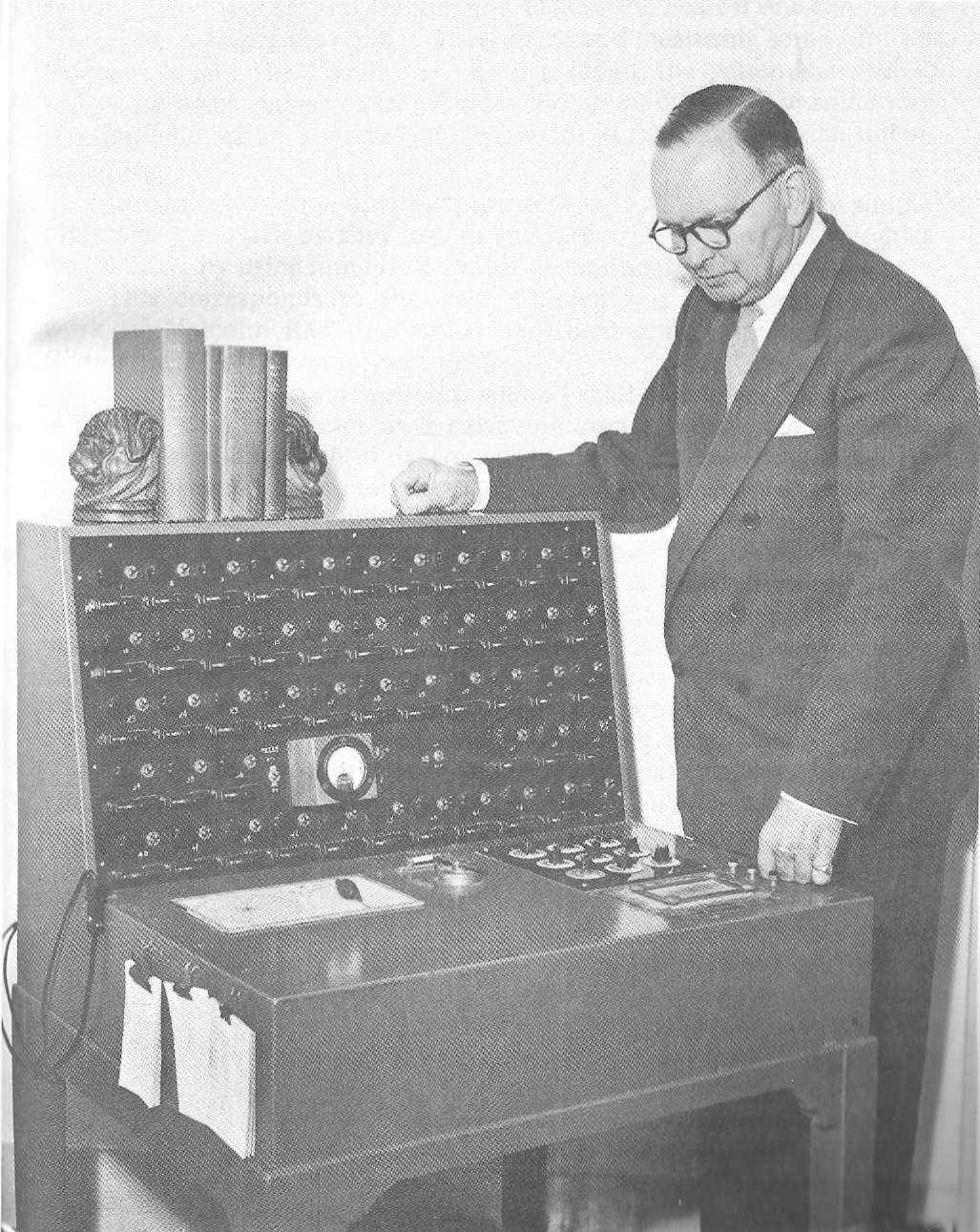
It is not until we come to inspect the Wilson instrument that we find a true electrical circuit. Here there are 50 individual dials on the upright panel, and a panel of 9 dials on the table.
The problem was how to convert a 9 dial ‘treatment rate’ on this latter panel to a single dial on the upright.
Wilson introduced what is known as a Wheatstone Bridge as a balancing circuit for this purpose, so that he could get a ratio of 9 to 1 on each of his dials on the main panel. This instrument came to be known as the ‘Wilson 51’ because 51 patients could be treated at the same time; and all with different rates. He also made a smaller model with 3 treatment circuits.
This again makes one consider ‘What is the energy one is using?’ In radionic diagnosis and treatment I believe the nearest one can get to an answer is to say that one is determining and measuring some form of frequency, and that, as far as one can judge, the patient’s ‘witness’ radiates a whole gamut of frequencies. These are disturbed in some way if a patient has an abnormal condition or is functioning in an unbalanced way.
In general, radionic instruments appear to work on a very simple principle, inasmuch as they try to interpret the regular and irregular frequencies, by using numerical and/or geometrical patterns of energy.
This corresponds to the theory which was incorporated in the work of Malcolm Rae, and which he describes fully in his Magnetic Geometrical Applications literature.
In my new instrument about which I shall comment, the principle of the Wheatstone Bridge as a balancing circuit is also used, but the mains power, to which it is connected, is solely for registering this balance through the meter, and for the inclusion of the Sine-wave method of increasing effects in treatment, and for earthing. As with Drown, radionic work does not require mains power.

